Open Shortest Path First
28 Oct 2020
OSPF Concept
- OSPF stands for Open Shortest Path First.
- Single and Multi area.
- Link-state routing protocol.
- Dijkstra’s algorithm calculates the cost, which is used to determine the best path to the destination.
- OSPF has faster convergence and scales to much larger networks compared to RIP.
- OSPFv2 is used for IPv4 networks, whereas OSPFv3 is used for IPv6 networks.
- “A Link” can be; an interface on a router, a connection between two routers or a stub network.
- All link-state information includes the network prefix, prefix length and cost.
- Router ID is a 32-bit dotted decimal address (e.g. 1.1.1.1)
- Dead Interval is typically four times (x4) the Hello Interval
- The reserved All OSPF Routers IPv4 multicast address is 224.0.0.5
- Only the DR and BDR listen for 224.0.0.6 (all designated routers).
Types of Packets
5 types of packets are used in OSPF:
| Type | Packet Name | Description |
|---|---|---|
| 1 | Hello | Discovers neighbours and builds adjacencies between them. - default every 10 seconds |
| 2 | Database Description (DBD) | Checks for database synchronisation between routers Contains an abbreviated list of the LSDB of the sending router |
| 3 | Link-State Request (LSR) | Requests specific link-state records from router to router |
| 4 | Link-State Update (LSU) | Sends specifically requested link-state records Contains 11 different LSAs |
| 5 | Link-State Acknowledgment (LSAck) | Acknowledges the other packet types |
Databases
The five packets are used to create and maintain 3 OSPF databases, which are stored in RAM:
| Database | Table | Description |
|---|---|---|
| Adjacency Database | Neighbour Table | List of all established neighbour routers. This table is unique for each router. * Can be viewed using the show ip ospf neighbor command. |
| Link-state Database | Topology Table | Lists information about all other routers in the network. This database represents the network topology. All routers within an area have identical LSDB.Can be viewed using the show ip ospf database command. |
| Forwarding Database | Routing Table | List of routes generated when an algorithm is run on the link-state database. The routing table of each router is unique and contains information on how and where to send packets to other routers. * Can be viewed using the show ip route command. |
Link-State Process
- Establish Neighbour Adjacencies
- Send Hello packet out all OSPF-enabled interfaces.
- OSPF-enabled router attempts to establish a neighbour adjacency
- Exchange Link-State Advertisements
- Routers then exchange link-state advertisements (LSAs)
- State
- Cost
- Adjacent neighbours receiving the LSA immediately flood the LSA to other directly connected neighbors, until all routers in the area have all LSAs.
- Routers then exchange link-state advertisements (LSAs)
- Build the Link State Database (LSDB)
- Execute the Dijkstra Shortest-Path First (SPF) algorithm on the built LSDB
- Choose the Best Route, this creates the Routing Table
Areas
- hierarchical routing using areas makes OSPF more efficient and scalable.
- OSPF areas are a grouping of routers that share the same link-state information.
- Multiarea OSPF
- All areas must connect to the backbone area (area 0)
- Routers interconnecting the areas are referred to as Area Border Routers (ABRs)
- Processor intensive routing operations, such as recalculating the database, are kept within an area.
Multiarea OSPF offers the following advantages:
- Smaller routing tables
- Reduced link-state update overhead
- Reduced frequency of SPF calculations
OSPFv3
- OSPFv3 is for exchanging IPv6 prefixes.
- OSPFv3 Address Families feature includes support for both IPv4 and IPv6.
- OSPFv3 has seperate processes from its IPv4 counterpart to run independently.
- OSPFv3 have separate adjacency tables, topology tables, and IP routing tables.
Link-State Updates
- Initial exchange of a Type 2 Database Description (DBD) packet.
- Type 3 Link-State Request (LSR) is used to request more/specific information about an entry.
- Type 4 Link-State Update (LSU) is used to reply to the Type 3 LSR.
- Type 5 Link-State Acknowlege (LSAck) is used to acknowledge the receipt of a Type 4 LSU
LSUs are also used to forward OSPF routing updates, such as link changes.
An LSU packet can contain 11 different types of OSPFv2 LSAs. OSPFv3 renamed several of these LSAs and also contains two additional LSAs.
| LSA Type | Description |
|---|---|
| 1 | Router LSAs |
| 2 | Network LSAs |
| 3 or 4 | Summary LSAs |
| 5 | Autonomous System External LSAs |
| 6 | Multicast OSPF LSAs |
| 7 | Defined for Not-So-Stubby Areas |
| 8 | External Attributes LSA for Border Gateway Protocol (BGPs) |
Hello Packet
OSPF Type 1 packet is the Hello packet. Hello packets are used to do the following:
- Discover OSPF neighbours and establish neighbour adjacencies.
- Advertise parameters on which two routers must agree to become neighbours.
- Elect the Designated Router (DR) and Backup Designated Router (BDR) on multiaccess networks like Ethernet. Point-to-point links do not require DR or BDR.
OSPF Operational States
| State | Description |
|---|---|
| Down State | 1. No Hello packets received = Down. 2. Router sends Hello packets. 3. Transition to Init state. |
| Init State | 1. Hello packets are received from the neighbour. * They contain the Router ID of the sending router. 2. Transition to Two-Way state. |
| Two-Way State | In this state, communication between the two routers is bidirectional. On multiaccess links, the routers elect a Designated Router (DR) and a Backup Designated Router (BDR). * Transition to ExStart state. |
| ExStart State | On point-to-point networks, the two routers decide which router will initiate the DBD packet exchange and decide upon the initial DBD packet sequence number. |
| Exchange State | 1. Routers exchange DBD packets. 2. If additional router information is required then transition to Loading; otherwise, transition to the Full state. |
| Loading State | 1. LSRs and LSUs are used to gain additional route information. 2. Routes are processed using the Dijkstra’s SPF algorithm. 3. Transition to the Full state. |
| Full State | The link-state database of the router is fully synchronised. |
Synchronising OSPF Databases
-
Decide first router
-
In the ExStart state
-
The router with the higher router ID will be the first router to send DBD packets
-
-
Exchange DBDs
- In the Exchange state
- Routers exchange one or more DBD packets
-
Send an LSR
- When a change is perceived (incremental updates)
- Every 30 minutes
Designated Router (DR) and Backup Designated Router
two challenges for OSPF regarding the flooding of LSAs, as follows:
-
Creation of multiple adjacencies -
-
Ethernet networks could potentially interconnect many OSPF routers over a common link.
-
Creating adjacencies with every router is unnecessary and undesirable.
-
It would lead to an excessive number of LSAs exchanged between routers on the same network.
-
-
Extensive flooding of Link-State Advertisements (LSA) -
- Link-state routers flood their LSAs any time OSPF is initialised, or when there is a change in the topology.
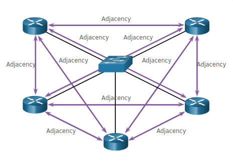
Calculate Number of Adjacenies: n ( n-1 ) / 2 = # Adjacenies
Example: 5 ( n-1 ) / 2 = 10 Adjacenies
The solution to managing the number of adjacencies and the flooding of LSAs on a multiaccess network is the DR.
OSPF elects a DR to be the collection and distribution point for LSAs sent and received.
OPSF v2 Configuration
Enable OSPF using the router ospf <process-id> within the global configuration mode, you will be taken into the router configuration mode.
R1(config)# router ospf 10
R1(config-router)#
A process ID can be between 1 and 65,535 and is significant to the individual router, this is not required to establish adjacencies.
A router ID is a 32-bit value, represented as an IPv4 address. The router ID uniquely identifies an OSPF router. The router ID can be assigned automatically or manually configured by an administrator.
R1(config-router)# router-id 1.1.1.1

R1# show ip protocols
Router ID Precedence (Election Process)
- The router ID is explicitly configured.
- The highest IPv4 address of any of configured loopback interfaces.
- The highest active IPv4 address of any of its physical interfaces.
The addition of a new router does not initiate a new election process.
Configuring a Loopback interface as the Router ID
R1(config-if)# interface Loopback 1
R1(config-if)# ip address 1.1.1.1 255.255.255.255
R1(config-if)# end
R1# show ip protocols | include Router ID
  Router ID 1.1.1.1
R1#
A 32-bit host route (255.255.255.255) would not get advertised as a route to other OSPF routers.
Modify a Router ID
An active OSPF router does not allow the router ID to be changed until the router is reloaded or the OSPF process is reset.
R1# clear ip ospf process
Reset ALL OSPF processes? [no]: y
Clearing the OSPF process is the preferred method to reset the router ID.
Wildcard Mask
Typically the inverse of the subnet mask configured.
The easiest method for calculating a wildcard mask is to subtract the network subnet mask from 255.255.255.255.
  255.255.255.255
- 255.255.255.0    (/24 subnet mask)
_________________
  000.000.000.255
Example:
Network:         192.168.226.96 /27
Subnet Mask:     255.255.255.224
Wildcard Mask:    0 . 0 . 0 . 31
Advertising Networks
There are two ways to advertise a network using the network command, the first is to use a wildcard to include all the network addresses or use 0.0.0.0 and the network address.
R1(config)# router ospf 10
R1(config-router)# network 10.10.1.0 0.0.0.255 area 0
R1(config-router)#
R1(config)# router ospf 10
R1(config-router)# network 10.10.1.1 0.0.0.0 area 0
R1(config-router)#
We can also directly configure OSPF on the interface using the ip ospf command.
R1(config-router)# interface GigabitEthernet 0/0/0
R1(config-if)# ip ospf 10 area 0
R1(config-if)#
Passive Interface
Passive interfaces prevent the transmission of routing messages through a particular interface.
R1(config)# router ospf 10
R1(config-router)# passive-interface loopback 0
R1(config-router)# end
R1# show ip protocols

Passive Interface(s):
    Loopback0
Point-to-Point Networks
By default OSPF will elect a DR and BDR on Ethernet interfaces, this election is unnecessary when there is a point-to-point (1-to-1) connection.
Using ip ospf network point-to-point on all interfaces we can disable the DR/BDR election process.
R1# show ip ospf interface GigabitEthernet 0/0/0

Network Type POINT_TO_POINT
Multi-access OSPF
Multi-access OSPF networks use an elected router to control the distribution of LSA (Link-State Advertisements).
Routers can be connected to the same switch to form a multi-access network. Ethernet LANs are the most common example of a multi-access network.
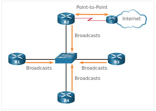
Designated Router
The DR is responsible for collecting and distributing LSAs sent and received using multicast IPv4 address 224.0.0.5
A BDR is also elected in case the DR fails. The BDR listens passively and maintains a relationship with all the routers.
All other routers become a DROTHER, using the multi-access address 224.0.0.6 which only the DR and BDR will listen.
- To verify the roles of the OSPFv2 router, use the
show ip ospf interfacecommand. - To verify the OSPFv2 adjacencies, use the
show ip ospf neighborcommand - To set the priority of an interface, use the command
ip ospf priority value, where 0 does not become a DR.
Cost Metric
Default Cisco OSPF Costs
| Interface Type | Reference Bandwidth in bps | Default Bandwidth in bps | Cost | |
|---|---|---|---|---|
| 10 Gigabiti Ethernet (10Gbps) | 100,000,000 | / | 10,000,000,000 | 0.01 = 1 |
| Gigabit Ethernet (1Gbps) | 100,000,000 | / | 1,000,000,000 | 0.1 = 1 |
| Fast Ethernet (100Mbps) | 100,000,000 | / | 100,000,000 | 1 |
| Ethernet (10Mbps) | 100,000,000 | / | 10,000,000 | 10 |
Because the OSPF cost value must be an integer, FastEthernet, Gigabit Ethernet, and 10 Gigabit Ethernet (10 GigE) interfaces share the same cost.
To correct this situation, you can:
- Adjust the reference bandwidth with the
auto-cost reference-bandwidth Mbpscommand on each OSPF router. - Manually set the OSPF cost value with the
ip ospf costcommand on necessary interfaces.
To return to the default reference bandwidth, use the auto-cost reference-bandwidth 100 command.
Default Route Propagation
Create a default route
R2(config)# ip route 0.0.0.0 0.0.0.0 s0/0/0
Use the OSPF originate command
R2(config)# router ospf 10
R2(config-router)# default-information originate
R2(config-router)# end
Verifying OSPF
The following two commands are particularly useful for verifying routing:
show ip interface brief- This verifies that the desired interfaces are active with correct IP addressing.show ip route- This verifies that the routing table contains all the expected routes.
Additional commands for determining that OSPF is operating as expected include the following:
show ip ospf neighbor- check the router has formed an adjacency.show ip protocols- quick way to verify vital OSPF configuration information.show ip ospf- examine the OSPFv2 process ID and router ID, area information and last SPF algorithm executed.show ip ospf interface- shows the process ID, the local router ID, the type of network, OSPF cost, DR and BDR information on multiaccess links, and adjacent neighbors.show ip ospf interface brief- shows a quick summary of OSPF enabled interfaces.