Lets Explore: Fibre Optics
The fundamentals of fibre optic networking, from single-mode and multimode fibre to SFP transceivers, connectors, cable types, splicing, and how fibre is deployed by Internet Service Providers.
What is Fibre Optics?
Fibre optics is a communication technology that transmits data using pulses of light rather than electrical signals.
Instead of travelling through copper wires, information is carried through an extremely thin strand of glass or plastic known as an optical fibre. The light is generated by a laser or LED inside an optical transceiver and travels along the fibre by continuously reflecting off the inner walls of the cable, a process known as Total Internal Reflection (TIR).
Because light suffers very little signal loss and is immune to electrical interference, fibre optics has become the preferred medium for modern enterprise networks, data centres, and Internet Service Provider (ISP) infrastructure.
Benefits of Fibre Optics
- Higher speed potential
- Lower attenuation (Loss of Signal Strength)
- Greater length
- Immune to:
- Electromagnetic Interference (EMI)
- Radio Frequency Interference (RFI)
- Lightning and Ground loops
- Less environmental impacts such as corrosion or moisture
- Increased security as fibre optic cable use light which is difficult to tap into without detection
Types of Fibre
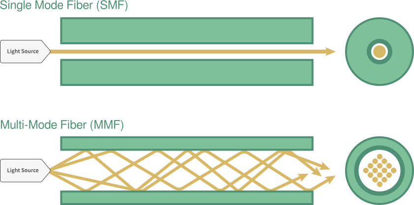
- Multimode Fibre (MMF)
- Cost effective
- Shorter reach 100-550m
- Typically installed Inside Plant (ISP)
- Single-mode Fibre (SMF)
- Longer-distance 10-80km+ (6-50 miles)
- Typically installed Outside Plant (OSP)
Optical modules matter, which will be discussed later in this post.
Grades
- OM - Optical Multimode
- OS - Optical Single-mode
Generally, newer fibre grades provide improved bandwidth and support higher data rates over longer distances. However, selecting the correct grade depends on the application rather than simply choosing the highest number available.
- OM1 - OM5
- OS1 - OS2
Grade Colours
The primary ways to the fibre cable grade include checking the cable jacket color, reading the print legend, and looking at their technical performance specifications.
- OM3 = Aqua (Turquoise blue)
- OM4 = Violet (Purple)
- OS2 = Yellow
Violet is widely used for OM4, you will still encounter plenty of installations where OM4 cables are aqua, so colour alone is not always a definitive test.
Fibre Optic Transceivers
Fibre optic transceivers are modules that plug into networking equipment such as switches, converting the light into electrical signals determining the:
- Speed
- Wavelength
- Transmission distance
- Connector type
Connector Types
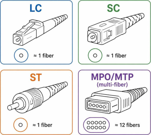
- LC - Lucent Connector
- Commonly used
- SFP, SFP+, QSFP
- Polarity sensitive
- SC - Subscriber Connector
- Old
- ST - Straight Tip
- Legacy
- MPO/MTP - Multi-fibre Push-on
- High-density multi-lane optics
- Polarity sensitive
- 8/12/24 lanes
Most fibre links use two fibres for Transmit (TX) and Receive (RX), this is known as Duplex fibre.
Some specialist optics, known as BiDi (Bidirectional) transceivers, transmit and receive over a single fibre using different wavelengths.
SFP
SFP stands for Small Form-Factor Pluggable.
QSFP stands for Quad SFP, 4 lanes.
| Form Factor | Connector | Speed | Lanes | Notes |
|---|---|---|---|---|
| SFP | LC Duplex | 1 Gb/s | 1 | Standard Small Form-factor Pluggable |
| SFP+ | LC Duplex | 10 Gb/s | 1 | Enhanced SFP for 10 Gigabit Ethernet |
| QSFP+ | MPO/MTP | 40 Gb/s (4 × 10 Gb/s) | 4 | Quad Small Form-factor Pluggable Plus |
| QSFP28 | MPO/MTP | 100 Gb/s (4 × 25 Gb/s) | 4 | Commonly used for 100Gb Ethernet |
| QSFP112 | MPO/MTP | 400 Gb/s (4 × 100 Gb/s) | 4 | Uses 112 Gb/s electrical lanes |
| QSFP-DD | MPO/MTP | 800 Gb/s (8 × 100 Gb/s PAM4) | 8 | Double Density (DD) with eight electrical lanes |
Optical reach class names
- SR = Short Reach, 300-550m
- LR = Long Reach, 10km
- ER = Extended Reach, 40km
- ZR/FR = Ultra-long Far Reach, 80km+
APC and UPC Connectors
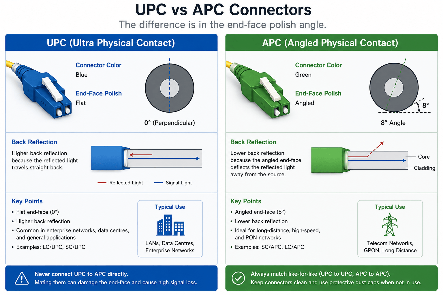
Single-mode connectors and modules are commonly available in two polish types.
- UPC (Blue)
- APC (Green)
APC connectors minimise reflected light and are widely used in GPON and ISP networks.
Never connect APC and UPC connectors together.
Fibre Care
Handling and Storage
Although fibre cabling is quite durable, you still need to take care when handling otherwise the glass strands can fracture.
You can test cables using a red light tester, if you can see the red light in the cable this means its potentially broken.
Also keep the end caps/covers on until the cable is being used, this helps to keep the connectors clean.
Lastly do not tangle cables, use a hook and loop fastener and avoid compressing the cable.
Cleaning
It’s important to ensure that fibre optic termination points are clean as they can become dirty when handling, resulting in attenuation of signal.
Tools
- Cleaning Pen
- Different pen for each connector
- Usable on patch panel ports
- Cassette Tape Cleaner
- Universal cleaner
- Not usable on patch panel port
- Cleaning Wipes
- Avoid wipes when you can use the pen or cassette
Below is an example of a dirty fibre connection, and the result of cleaning it.

Safety
Never look directly into the end of a fibre optic cable or optical transceiver.
Many optical modules transmit infrared laser light which is invisible to the human eye but can permanently damage your eyesight.
Always use a fibre inspection scope or optical power meter rather than looking directly into a connector.
Fibre Cable
There are four types of fibre cable, each has their specific usage
- Loose Tube
- Tight Buffered
- Corrugated Steel Tape - CST
- Steel Wire Armour - SWA
| Feature | Loose Tube | Tight Buffered | CST | SWA |
|---|---|---|---|---|
| Primary Environment | Outdoor / Long-distance | Indoor / LANs | Outdoor / Underground | Extreme / Industrial / Heavy-duty |
| Water Protection | Yes (Gel or powder filled) | No (Relies on indoor jackets) | Yes | Yes |
| Crush / Rodent Resistance | Low to Moderate | Low | High (Crush & Rodent) | Extremely High |
| Termination Ease | Harder (Requires gel cleaning) | Easier (No gel) | Moderate (Requires stripping armor) | Harder (Requires specialized glands) |
Splicing
Splicers
Fibre optic splicers are precision tools used to join glass fibres together
- Core Alignment Fusion Splicers
- High-precision alignment of the core
- Used for long-distance trunk lines, data centres and ultra-low signal loss networks.
- Cladding Alignment Fusion Splicers
- Aligns the outer cladding
- Used for FTTH, LANs where zero-loss precision is not priority.
- Ribbon Fusion Splicers
- Splices multiple fibres simultaneously
- Used for backbone networks, data centres and telecom providers
- Mechanical Splice
- Uses an alignment sleeve and gel to hold two fibre cables
- Used for emergency repairs.
Steps to Splice
- Add a protective sleeve to the fibre
- Strip the cable to expose the fibre cores
- Clean the bare fibre with 99.9% isopropyl alcohol (IPA)
- Fuse the fibre using the splicer
- Slide the sleeve into position and heat to shrink
Tools
There are a few tools that can be extremely useful, for example:
- Optical Light Source
- Optical Power Meter
- Optical Time-Domain Reflectometer (OTDR)
Each tool gets progressively adds more features and functinality but also becomes more expensive.
Optical Light Source
This device produces a light source, and when connected to a fibre optical cable you can see if the light is reaching the other end or if there are breakages within the cable, as shown in the image below.
As you can see the light does reach the end of the cable, but its leaking out from a potential break in the fibre, this will lead to signal loss.
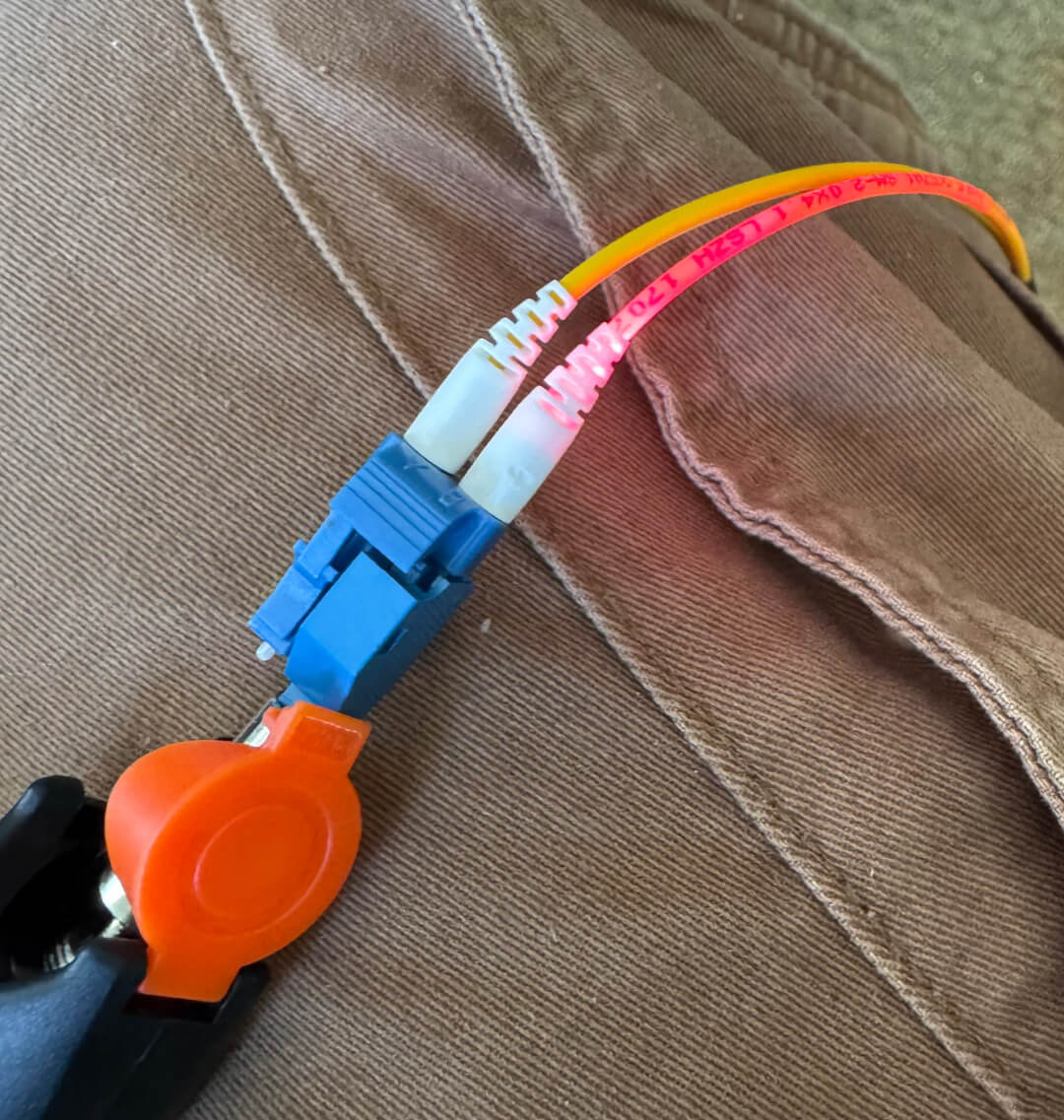
Optical light sources come in different forms, but the pen/flashlight is quite popular. In the photograph above I was using the 30KM Visual Fault Locator Fiber Optic Tester from Amazon.
Optical Power Meter
Power meters measure the measure the power level of light traveling within the fibre cable. A reading is shown in dBm and can be used to detect loss/attenuation in cables or connectors.
You’ll need to compare the provided measurement against the speicifcation sheet for the cable or connector.
I have the Comptyco Optical Power Meter value device from Amazon, it also has a light source built-in.
Optical Time-Domain Reflectometer (OTDR)
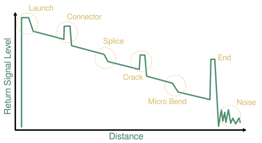
Measures the relected light to identify fibre characteristics such as:
- Length
- Attenuation
- Bend, Cracks, Connectors at what distance.
The meter produces a graph, similar to the graphic below.
You can buy cheap OTDRs from Amazon, but you are doing this professionally, then I’d suggest investing in quality tools.
Service Provider Installation
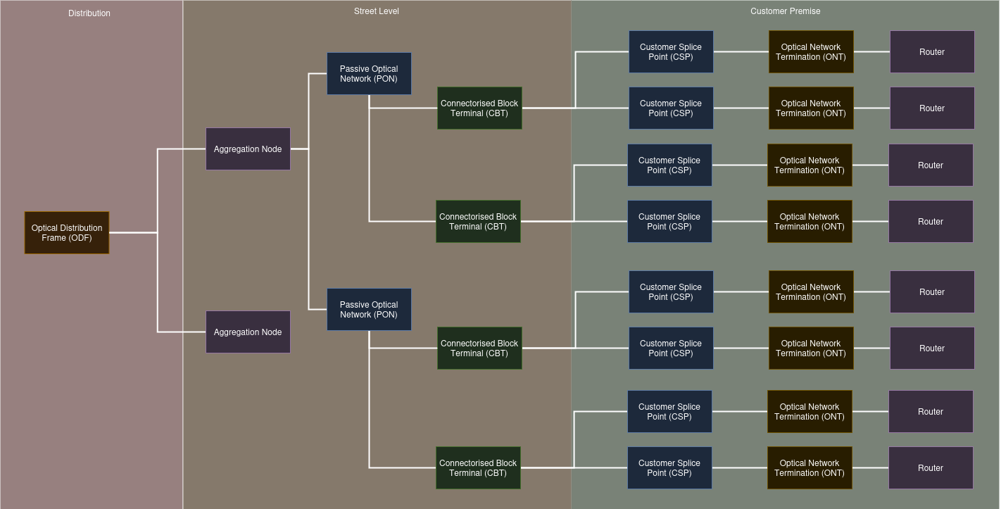
Optical Distribution Frame (ODF) is the connection between the ISPs distribution network and the access network.
The aggregation node takes the large capacity fibre cable and connects to a splitter or Passive Optical Network (PON), which allows the single fibre to be split into 32 connections.
The connection then continues to a Connectorised Block Terminal (CBT), before terminating at a Customer Splice Point (CSP).
The CSP then connects to an Optical Network Terminal (ONT), then finally the router.
Below are some videos demonstrating Openreach’s fibre deployment.
Common Fibre Issues
| Problem | Possible Cause |
|---|---|
| No Link | Wrong optic |
| High CRC Errors | Dirty connector |
| Intermittent Link | Excessive bend radius |
| High Attenuation | Damaged cable |
| No Light | Faulty SFP |
| Link Down | TX/RX reversed |